Advance Ultrasonic Testing(AUT)
UIC is a leader in the Ultrasonic Testing and Training industry. Experience, high skill levels and state of the art equipment keep us ready to handle any inspection applications. UIC can support your company with all your advanced ultrasonic needs with tools such as TOFD, Phased Array, Eddy Current tube inspections, and innovative inspection applications such as Phased Array Bolt inspection. Our State of the Art ultrasonic equipment can assist with detection of environmental, in-service damages and pre-service inspections of vessels and pipelines in the Petro-Chemical, Refining, Offshore and Power generation industries.
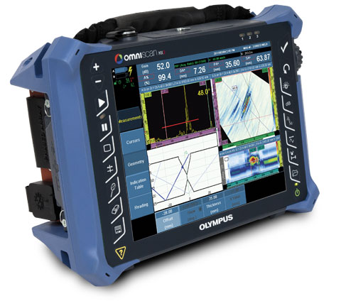
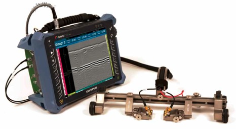
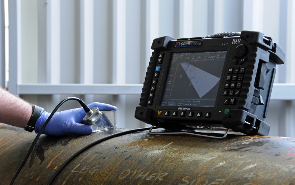
Advanced Applications: Flaw Sizing, Stress Corrosion Cracking (SCC) detection, Hydrogen Induced Cracking (HIC), Inline Inspection verification (ILI), Internal/External Metal Loss, Tank Floor Mapping, corrosion mapping Phased Array/Automatic Ultrasonic Testing (PAUT) is an advanced method of ultrasonic testing utilizing a specialized transducer with multiple elements enabling electronic beam steering to scan a test area. Comprehensive software compiles the test data creating a visual image map of the material and inspection findings. Corrosion Mapping utilizes the accuracy of our phased array equipment employed one crawler to create a highly accurate computer generated image map of large areas of material scanned.
Ultrasonic Phased Array (PAUT)
Phased array can successfully overcome many of the inconsistencies of the manual application. A
phased array probe is constructed from a number of very small elements arranged in a line or in
a specific cluster design. By activating a number of the elements at once and applying specific
voltages to each element a predetermined beam angle, or beam of varying angles can be
produced.
Furthermore, by moving the active elements along the probe the beam is moved forward/backward in
a manner similar to the movement of a manual technique.
When the phased array wedge is placed on the parent material at a specific stand-off position
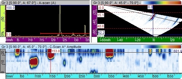
and moved along the weld, data can be collected and imaged as a C-scan (plan view) of the weld,
much like a traditional radiograph. To compliment this, the ultrasonic imaging system can also
show the A-scan, a B-scan (end view), a D-scan (side view) and in the case of a beam with
varying angles an S-scan (or sectorial scan).

Time Of Flight Difrraction (TOFD)
Although time-of-flight diffraction (TOFD) can be used for a variety of applications, its
primary use is rapid weld testing of circumferential and axial weld seams, also known as
perpendicular TOFD scanning. Since the introduction of TOFD in the 1970s, the use of this
reputed reliable nondestructive testing technique has steadily increased. Manual execution is
possible with TOFD, however, it is most commonly performed in combination with a recording
device, that is, an encoder or industrial scanner. To achieve code compliance in North America,
TOFD is often coupled with pulse-echo or phased array techniques in order to cover the root and
cap regions of the weld.
TOFD is usually performed using longitudinal waves as the primary detection method. Ultrasonic
sensors are placed on each side of the weld. One sensor sends the ultrasonic beam into the
material and the other sensor receives reflected and diffracted ultrasound from anomalies and
geometric reflectors. TOFD provides a wide area of coverage with a single beam by exploiting
ultrasonic beam spread theory inside the wedge and the inspected material. When the beam comes
in contact with the tip of a flaw, or crack, diffracted energy is cast in all directions.
Measuring the time of flight of the diffracted beams enables accurate and reliable flaw
detection and sizing, even if the crack is off-oriented to the intial beam direction. During
typical TOFD inspections, A-scans are collected and used to create B-scan (side view) images of
the weld. Analysis is done on the acquisition unit or in post-analysis software, positioning
cursors to measure the length and through-wall height of flaws.

Benifits of TOFD
1.Based on diffraction, so relatively indifferent to weld bevel angles and flaw orientation.
2.Uses time of arrival of signals received from crack tips for accurate defect positioning and
sizing.
3.Precise sizing capability makes it an ideal flaw monitoring method.
4.Quick to set up and perform an inspection, as a single beam offers a large area of
coverage.
5.Rapid scanning with imaging and full data recording.
6.Can also be used for corrosion inspections.
7.Required equipment is more economical than phased array, due to conventional nature (single
pulser and reciever) and use of conventional probes.
8.Highly sensitive to all weld flaw types.
Advance Ultrasonic Testing(AUT) at UIC, Jubail, KSA.
1. Advance Ultrasonic Testing(AUT) equipment like mentioned below:
• Pahsed array unit
• TOFD unit
• TOFD+PAUT combination unit
• All kind of required scanner
2. Experienced PAUT/TOFD inspector for carry out difficult configuration of welds.
3. Experienced in house ASNT NDT Level III and experts for providing techniques establishment, procedure preparation, approval and consultancy services
4. ASNT NDT Level III trainers for conducting in house or external NDT Level 2 training and certification courses on Ultrasonic testing and other NDT inspection methods. Read more about Ultrasonic Testing Personnel Certifications.
5. PAUT/TOFD inspectors qualified and certified to Level II as per ASNT recommended practice SNT-TC-1A is approved & also BINDT (British institute of nondestructive testing) approved Level-II according to ISO 9712:2012 for carry out inspection.


